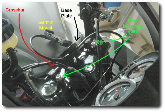
The GadgetGuy system consists of 2 pieces - a motorcycle specific universal bracket and a GPS specific base plate. While a specific universal bracket sounds like an oxymoron, the basic brackets are the same, but the crossbar length, mounting bolts etc. depend upon the specific motorcycle.
For the Sprint GT, the order consisted of
The last item was an optional purchase, as I thought it might be useful to raise the GPS higher. As it turns out, that is not required, but also it does not fit onto a Sprint as the crossbar just clears the nut on the triple clamp leaving no room for the swivel joint if you want the GPS centred. And the Zumo 660 does need to be centred, as it occupies most of the space between the clip ons. The clearance could be fixed with additional spacers and longer mounting bolts, I expect.
As the clip ons are black, I ordered the anodised black versions of the above. The quality of the components is excellent, as is the packaging, with everything in sealed plastic bags. It also includes a large collection of screws, and several allen keys. Colour me impressed.
These are items that need to be done at some stage, and upfront is as good a time as any. Specifically this involves adapting the cable wired to the Garmin GPS mount. The changes are minor, and may not be applicable to your application.
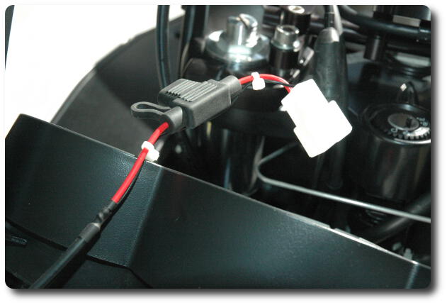
The first step is to make up a short cable to be connected to the bike's wiring harness at the back of the instrument panel. One end of this cable has a 2 pin female, automotive style, connector attached to it. A matching male connector is attached to the cable from the GPS mount. This cable requires 2 wires (one red, one black), each about 15cm (5 inches) long. When the the new cable is plugged into the Garmin cable, the red wire from the Garmin needs to connect to the red wire in the new cable.
The Garmin GPS cable comes with 2 audio connectors, a mini USB connector and the two power leads. The audio and USB connectors are of no use to me, so they were sealed up with a silicone product that happened to be on hand. It must not be conductive! Squeeze some onto a piece of paper; allow to dry a little then measure its resistance if you are in doubt.
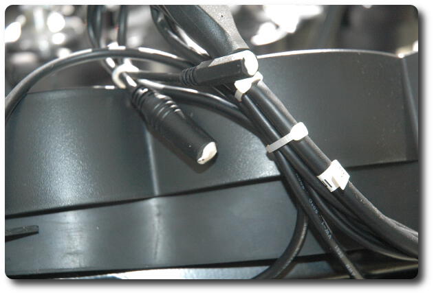
The audio connectors all sealed up.
Preparation work done, it's time to start on the bike. There are 2 parts to mounting - one is the physical position, which is mostly determined. Fine tuning can take a while, but there's little question about where it goes. The second component is an electrical connection.
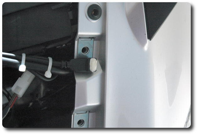
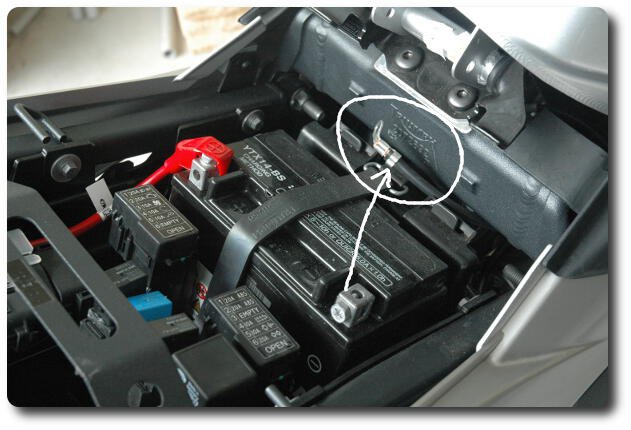
First step is to disconnect the battery. Remove the seat, and undo the screw holding the ground (negative) cable to the battery. Tuck the cable out of the way, as shown here on the right side, to prevent an accidental re-connection. The other, red, cable can safely be left connected.
Now is a good time to remove the windscreen - doing so allows easier access to the triple clamp and prevents accidental damage while working on the triple clamp. There are 6 obvious screws holding the windscreen in place. Remove those, ensuring the screen does not fall off. Place the screws and screen out of harm's way.
Attach the base plate to the crossbar from the bracket kit. Centre the bracket in the middle of the crossbar, and tighten up the mounting bolts. Two of these become unreachable once the crossbar is mounted on the triple clamp. And a third is covered by the cable from Garmin's mounting base. Note that the crossbar can be rotated later to set the desired angle of view of the Zumo.
Feed the cable from the Garmin mounting base through the cable clip on the back of the base plate. This is not easily reached once on the bike.
Note: I did not think of this at the time, but now that the base plate is securely attached to the crossbar, it is easy to screw the Garmin mount onto the base plate now!
Remove the two front bolts attaching the clip ons to the triple clamp. I tried using the rear bolts, but it just doesn't work out.
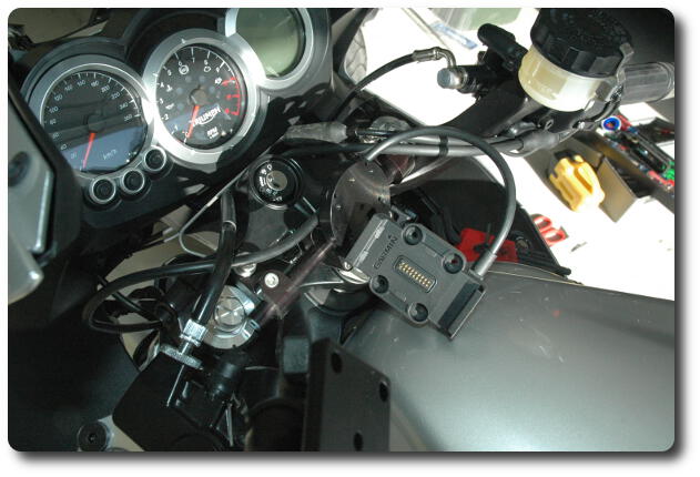
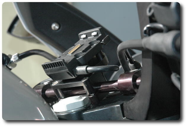
Slip the swivel jouints onto the crossbar, then insert the mounting bolts and spacers into the two holes from which you just removed the bolts, i.e. the front mounting bolts for the clip ons. You should have something like this:-
Once you are happy with the position, tighten up the mounting bolts to 15 Nm.
Attach the Garmin bracket to the base plate. There are 4 bolts required for this, and 4 spacers. I also used the washers Garmin supplied with their kit. Rotate the base plate to be as horizontal as possible. I inserted the bolt + washer + Garmin bracket + spacer into one hole and screwed it up loosely. Repeat for the remaining 3. It's a bit awkward on the last one, as the Garmin bracket is reasonably constrained even with loose screws. When all are in position, tighten the screws. You should now see something like these:-
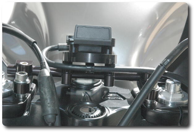
The view of the mount from the front, showing the cable anchor underneath
the base plate. Note that the cable clamp is not a tight fit on the cable,
but it does maintain it in a stable location.
Time to start on the electrical side.